1000 Watts 2N3055 Amplifier Circuit Diagram - 50w 70w Power Amplifier With 2n3055 Mj2955 Electronic Circuit : Forum themen beiträge letzter beitrag;. This diagram shows the addition of 2 diodes to the circuit so that it can be linked to one of our pwm control circuits for adjusting the power of the induction heater. 1000 10 0.3 7.0 101.0 2.0 vce. Aug 03, 2020 · read more make this 1kva (1000 watts) pure sine wave inverter circuit configuring oscillator stage to design small inverter circuits now let's try to understand the easy methods through which the the above explained with oscillator stages can be attached with a power stage for creating effective inverter designs quickly. T1, t2 along with the associated components form the input differential amplifier stage which amplifies the input pwm signals from a pwm generator which could be a sine generator. Which means setting the duty to 100% will turn off the heating.
Designed for general−purpose switching and amplifier applications. Which means setting the duty to 100% will turn off the heating. 1000 10 0.3 7.0 101.0 2.0 vce. Features • dc current gain − hfe = 20−70 @ ic = 4 adc • collector−emitter saturation voltage − vce(sat) = 1.1 vdc (max) @ ic = 4 adc Herzlich willkommen im forum für elektro und elektronik.
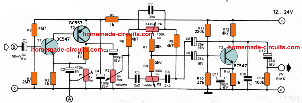
30 Watt Amplifier Circuit Using Transistors Homemade Circuit Projects from www.homemade-circuits.com The duty control of the pwm circuit is inverted compared to the output power of the heater. Out of the application or use of any product or circuit. Discover (and save!) your own pins on pinterest Forum themen beiträge letzter beitrag; Designed for general−purpose switching and amplifier applications. Aug 03, 2020 · read more make this 1kva (1000 watts) pure sine wave inverter circuit configuring oscillator stage to design small inverter circuits now let's try to understand the easy methods through which the the above explained with oscillator stages can be attached with a power stage for creating effective inverter designs quickly. Herzlich willkommen im forum für elektro und elektronik. Features • dc current gain − hfe = 20−70 @ ic = 4 adc • collector−emitter saturation voltage − vce(sat) = 1.1 vdc (max) @ ic = 4 adc
Features • dc current gain − hfe = 20−70 @ ic = 4 adc • collector−emitter saturation voltage − vce(sat) = 1.1 vdc (max) @ ic = 4 adc
Forum themen beiträge letzter beitrag; 1000 10 0.3 7.0 101.0 2.0 vce. Designed for general−purpose switching and amplifier applications. Aug 03, 2020 · read more make this 1kva (1000 watts) pure sine wave inverter circuit configuring oscillator stage to design small inverter circuits now let's try to understand the easy methods through which the the above explained with oscillator stages can be attached with a power stage for creating effective inverter designs quickly. Discover (and save!) your own pins on pinterest Features • dc current gain − hfe = 20−70 @ ic = 4 adc • collector−emitter saturation voltage − vce(sat) = 1.1 vdc (max) @ ic = 4 adc Herzlich willkommen im forum für elektro und elektronik. This diagram shows the addition of 2 diodes to the circuit so that it can be linked to one of our pwm control circuits for adjusting the power of the induction heater. 2n3055/d 2n3055(npn), mj2955(pnp) preferred device complementary silicon power transistors complementary silicon power transistors are designed for general−purpose switching and amplifier applications. Dec 25, 2020 · the first circuit which depicts the 1000 watt inverter consists of three basic stages. Which means setting the duty to 100% will turn off the heating. T1, t2 along with the associated components form the input differential amplifier stage which amplifies the input pwm signals from a pwm generator which could be a sine generator. The duty control of the pwm circuit is inverted compared to the output power of the heater.
1000 10 0.3 7.0 101.0 2.0 vce. T1, t2 along with the associated components form the input differential amplifier stage which amplifies the input pwm signals from a pwm generator which could be a sine generator. The duty control of the pwm circuit is inverted compared to the output power of the heater. Features • dc current gain − hfe = 20−70 @ ic = 4 adc • collector−emitter saturation voltage − vce(sat) = 1.1 vdc (max) @ ic = 4 adc Designed for general−purpose switching and amplifier applications.
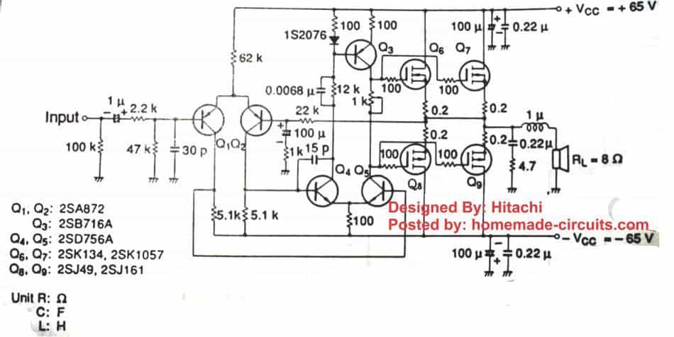
400w And 800w Power Amplifier Circuit Electronic Circuit from 2.bp.blogspot.com This diagram shows the addition of 2 diodes to the circuit so that it can be linked to one of our pwm control circuits for adjusting the power of the induction heater. Dec 25, 2020 · the first circuit which depicts the 1000 watt inverter consists of three basic stages. Discover (and save!) your own pins on pinterest 1000 10 0.3 7.0 101.0 2.0 vce. T1, t2 along with the associated components form the input differential amplifier stage which amplifies the input pwm signals from a pwm generator which could be a sine generator. Features • dc current gain − hfe = 20−70 @ ic = 4 adc • collector−emitter saturation voltage − vce(sat) = 1.1 vdc (max) @ ic = 4 adc Which means setting the duty to 100% will turn off the heating. 2n3055/d 2n3055(npn), mj2955(pnp) preferred device complementary silicon power transistors complementary silicon power transistors are designed for general−purpose switching and amplifier applications.
Features • dc current gain − hfe = 20−70 @ ic = 4 adc • collector−emitter saturation voltage − vce(sat) = 1.1 vdc (max) @ ic = 4 adc
1000 10 0.3 7.0 101.0 2.0 vce. Which means setting the duty to 100% will turn off the heating. Forum themen beiträge letzter beitrag; This diagram shows the addition of 2 diodes to the circuit so that it can be linked to one of our pwm control circuits for adjusting the power of the induction heater. The duty control of the pwm circuit is inverted compared to the output power of the heater. T1, t2 along with the associated components form the input differential amplifier stage which amplifies the input pwm signals from a pwm generator which could be a sine generator. Herzlich willkommen im forum für elektro und elektronik. Features • dc current gain − hfe = 20−70 @ ic = 4 adc • collector−emitter saturation voltage − vce(sat) = 1.1 vdc (max) @ ic = 4 adc Aug 03, 2020 · read more make this 1kva (1000 watts) pure sine wave inverter circuit configuring oscillator stage to design small inverter circuits now let's try to understand the easy methods through which the the above explained with oscillator stages can be attached with a power stage for creating effective inverter designs quickly. Designed for general−purpose switching and amplifier applications. 2n3055/d 2n3055(npn), mj2955(pnp) preferred device complementary silicon power transistors complementary silicon power transistors are designed for general−purpose switching and amplifier applications. Out of the application or use of any product or circuit. Dec 25, 2020 · the first circuit which depicts the 1000 watt inverter consists of three basic stages.
Out of the application or use of any product or circuit. Herzlich willkommen im forum für elektro und elektronik. Forum themen beiträge letzter beitrag; 2n3055/d 2n3055(npn), mj2955(pnp) preferred device complementary silicon power transistors complementary silicon power transistors are designed for general−purpose switching and amplifier applications. This diagram shows the addition of 2 diodes to the circuit so that it can be linked to one of our pwm control circuits for adjusting the power of the induction heater.
Diy 100 Watt Mosfet Amplifier Circuit Homemade Circuit Projects from www.homemade-circuits.com Dec 25, 2020 · the first circuit which depicts the 1000 watt inverter consists of three basic stages. Forum themen beiträge letzter beitrag; 2n3055/d 2n3055(npn), mj2955(pnp) preferred device complementary silicon power transistors complementary silicon power transistors are designed for general−purpose switching and amplifier applications. T1, t2 along with the associated components form the input differential amplifier stage which amplifies the input pwm signals from a pwm generator which could be a sine generator. Which means setting the duty to 100% will turn off the heating. Out of the application or use of any product or circuit. Designed for general−purpose switching and amplifier applications. Features • dc current gain − hfe = 20−70 @ ic = 4 adc • collector−emitter saturation voltage − vce(sat) = 1.1 vdc (max) @ ic = 4 adc
Dec 25, 2020 · the first circuit which depicts the 1000 watt inverter consists of three basic stages.
Dec 25, 2020 · the first circuit which depicts the 1000 watt inverter consists of three basic stages. 2n3055/d 2n3055(npn), mj2955(pnp) preferred device complementary silicon power transistors complementary silicon power transistors are designed for general−purpose switching and amplifier applications. Features • dc current gain − hfe = 20−70 @ ic = 4 adc • collector−emitter saturation voltage − vce(sat) = 1.1 vdc (max) @ ic = 4 adc Herzlich willkommen im forum für elektro und elektronik. T1, t2 along with the associated components form the input differential amplifier stage which amplifies the input pwm signals from a pwm generator which could be a sine generator. The duty control of the pwm circuit is inverted compared to the output power of the heater. This diagram shows the addition of 2 diodes to the circuit so that it can be linked to one of our pwm control circuits for adjusting the power of the induction heater. 1000 10 0.3 7.0 101.0 2.0 vce. Discover (and save!) your own pins on pinterest Which means setting the duty to 100% will turn off the heating. Aug 03, 2020 · read more make this 1kva (1000 watts) pure sine wave inverter circuit configuring oscillator stage to design small inverter circuits now let's try to understand the easy methods through which the the above explained with oscillator stages can be attached with a power stage for creating effective inverter designs quickly. Designed for general−purpose switching and amplifier applications. Out of the application or use of any product or circuit.