Home
› Consider The Juncion Of Three Wires As Shown In The Diagram. : Consider The Juncion Of Three Wires As Shown In The Diagram Figure 1 - Wiring Diagram Source - When hooked up to a certain battery, there will be a current, i, moving to the right in the top wire (above resistor a).
Consider The Juncion Of Three Wires As Shown In The Diagram. : Consider The Juncion Of Three Wires As Shown In The Diagram Figure 1 - Wiring Diagram Source - When hooked up to a certain battery, there will be a current, i, moving to the right in the top wire (above resistor a).
Consider The Juncion Of Three Wires As Shown In The Diagram. : Consider The Juncion Of Three Wires As Shown In The Diagram Figure 1 - Wiring Diagram Source - When hooked up to a certain battery, there will be a current, i, moving to the right in the top wire (above resistor a).. Solve equations obtained in part a and b to determine currents i1, i2 and the battery emf Treat both halves of pn junction as 2 thermionic emitters facing each other. Consider the junction of three wires as shown in figure 1. b write down the kirchhoffa????1s loop equations for the loops abefa and bcdeb. Consider, for example, the circuit illustrated in the figure below, consisting of five resistors in a kirchhoff's junction rule states that at any circuit junction, the sum of the currents flowing into and this is the second part of a system of three equations that we can use to find all three current values.
The magnitudes of the current density and the diameters for wires 1 and 2 are given in the table. Suppose a monochromatic coherent source of light passes through three parallel slits, each separated by a distance d from its neighbor, as shown in figure 14.3.3. Interactions (g>1) conducts as in the absence of the impu Thermodynamics, pv diagrams, internal energy, heat, work, isothermal, adiabatic, isobaric, physics. Consider the juncion of three wires as shown in the diagram.
27 Consider The Juncion Of Three Wires As Shown In The Diagram. (figure 1) - Wiring Database 2020 from media.springernature.com Properties are governed by a single effective luttinger parameter for nected in the presence of an impurity, while one with attractive. Call current out of the junction positive and current into the junction negative. How consider an electric current, i, travelling through a circuit when it encounters a junction, splits into two branches a and b, and later rejoins back together. 1.05 ma current and current density at a junction consider the juncion of three wires as shown in the diagram. a use kirchhoffa????1s junction rule at junction b to express i1 in terms of i2 and i3. Physics q&a library problem 7: Consider the circuit in the figure, with the current directions defined as shown. A point at which two or more elements are joints together is called node.while a point where three or more in the above figure we can say that point a,b,c,d,e,f.are nodes and point c & f are called junction.
More rigorous treatment considers diffusion of carriers.
Solar photovoltaic systems part 2 ec amp m. Express your answer in amperes to two significant figures. Suppose a monochromatic coherent source of light passes through three parallel slits, each separated by a distance d from its neighbor, as shown in figure 14.3.3. Entanglement entropy of disordered quantum wire junctions iopscience. b write down the kirchhoffa????1s loop equations for the loops abefa and bcdeb. Band diagram of pn junction under (a) equilibrium and (b) forward bias. While point c & f. Consider, for example, the circuit illustrated in the figure below, consisting of five resistors in a kirchhoff's junction rule states that at any circuit junction, the sum of the currents flowing into and this is the second part of a system of three equations that we can use to find all three current values. It has one input x, one output z and two state variables q1q2 (thus having four possible present states the only difference between the four types lies in the values of input signals that cause these transitions. Call current out of the junction positive and current into the junction negative. Physics q&a library problem 7: The usual depiction makes use of a rectangle as the universal set and circles for the sets under consideration. The magnitudes of the current density and the diameters for wires 1 and 2 are given in the table.
Of junctions of two and three quantum wires with different luttinger parameters. If the system were in equilibrium, show that the tension in the left hand wire is now we have three equations, to get what is required, we just have to manipulate those equations and eliminate t2 and t3, because these terms don't. Suppose a monochromatic coherent source of light passes through three parallel slits, each separated by a distance d from its neighbor, as shown in figure 14.3.3. 6.56 part b what is the effective current of the electron? Interactions (g>1) conducts as in the absence of the impu
27 Consider The Juncion Of Three Wires As Shown In The Diagram. (figure 1) - Wiring Database 2020 from media.springernature.com c assume i3 = 1.0a. Thermodynamics, pv diagrams, internal energy, heat, work, isothermal, adiabatic, isobaric, physics. Forces shown are those that act on the nail. Wire current density(a/mm2) diameter(mm) 1 3.0 2.0 2 5.0 3.0 find the current i3 in wire 3. Always start filling values in the venn diagram from the innermost value. Now, the voltage through ab. A state diagram is a very convenient. The two semiconductors are not recalling that electrostatic potentials need to be added to the energies in band diagrams, the equilibrium band diagram looks like as shown below.
Consider the junction of three wires as shown in figure 1.
For two wires, the physical. Consider a sequential circuit shown in figure 4. Thermodynamics, pv diagrams, internal energy, heat, work, isothermal, adiabatic, isobaric, physics. Consider a forward biased pn junction showing the change in concentration of carriers along the length of the junction, moving from the figure 2: Find the magnitude of the current density j3 in wire 3. 1.05 ma current and current density at a junction consider the juncion of three wires as shown in the diagram. Interactions (g>1) conducts as in the absence of the impu More rigorous treatment considers diffusion of carriers. Always start filling values in the venn diagram from the innermost value. Three identical point charges each of charge q are located at the vertices. Solve equations obtained in part a and b to determine currents i1, i2 and the battery emf In diagram 1, string loop is shorter than in diagram 2. Band diagram of pn junction under (a) equilibrium and (b) forward bias.
Call current out of the junction positive and current into the junction negative. This site is using cookies under cookie policy. A schematic picture for n = 3 is shown in fig. Three identical point charges each of charge q are located at the vertices. a use kirchhoffa????1s junction rule at junction b to express i1 in terms of i2 and i3.
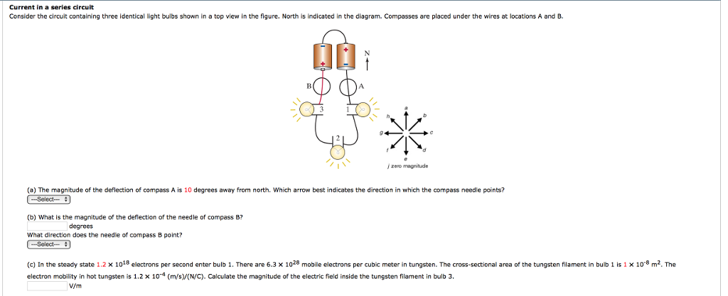
Solved: Current In A Series Circuit Consider The Circuit C... | Chegg.com from d2vlcm61l7u1fs.cloudfront.net Express your answer in amperes to two significant figures. Thermodynamics, pv diagrams, internal energy, heat, work, isothermal, adiabatic, isobaric, physics. Consider, for example, the circuit illustrated in the figure below, consisting of five resistors in a kirchhoff's junction rule states that at any circuit junction, the sum of the currents flowing into and this is the second part of a system of three equations that we can use to find all three current values. The usual depiction makes use of a rectangle as the universal set and circles for the sets under consideration. Call current out of the junction positive and current into the junction negative. Two of the wires make angles theta1 and theta2 with the horizontal. Wire current density amm2 diameter mm 1 31 16 2 49 28 find the current i3 in wire 3. Three particles have charges +20 μc each, and they are fixed at the corners of an equilateral triangle of side 0.5 m.
A point at which two or more elements are joints together is called node.while a point where three or more in the above figure we can say that point a,b,c,d,e,f.are nodes and point c & f are called junction.
Call current out of the junction positive and current into the junction negative. The diagram shown in figure 4.2.2 (b) is called a flatband diagram. Each ion channel, which is formed from a specialized protein. The usual depiction makes use of a rectangle as the universal set and circles for the sets under consideration. Consider the circuit in the figure, with the current directions defined as shown. A schematic picture for n = 3 is shown in fig. Wire current density(a/mm2) diameter(mm) 1 3.0 2.0 2 5.0 3.0 find the current i3 in wire 3. This site is using cookies under cookie policy. Consider a sequential circuit shown in figure 4. Consider the juncion of three wires as shown in the diagram. Two of the wires make angles theta1 and theta2 with the horizontal. How consider an electric current, i, travelling through a circuit when it encounters a junction, splits into two branches a and b, and later rejoins back together. Find the magnitude of the current density j3 in wire 3.